Part 1 of 3: Tension Control on Spindle Wheel
Introduction
Electronic gearing in motion control allows for a slave axis to follow a master axis with a programatically set gear ratio. There are certain applications that obviously lend to an electronic gearing solution, but there are some challenging applications where the functionality of electronic gearing can greatly simplify a solution in a manner that may not seem obvious at first. This series of three papers will discuss how electronic gearing can provide simple solutions to different motion control challenges. The second and third installments will provide solutions to the problems of making precision adjustments for a cutting axis on a high-speed material feed, and image drawing or writing on a moving conveyor system.
Definition
This first scenario deals with the problem of maintaining tension on a winding application. Figure 1 below shows a master reel feeding a slave reel with a tension sensor on the material. To maintain a specific tension, the slave axis must be geared to the master axis with a certain gear ratio. The main challenge comes when the feed-rate varies with the changing diameters of the master and slave axes as the material leaves the master and is wound on the slave. Therefore, what is required is a control loop using tension feedback to adjust the effective gear ratio.
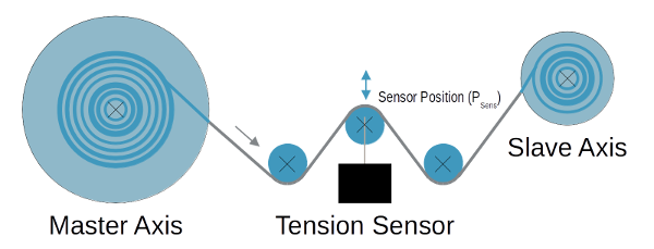
Figure 1: System setup
Resolution
One method to solve this problem is to directly change the gear ratio based on the tension feedback. The second method is to simplify the application down to two, superimposed motion profiles: tension control, and a geared profile with a static gear ratio. This paper will detail the second of these two methods.
Tension Control
Tension control requires a control loop similar to the position loop used in servo control systems, shown below in Figure 2. The position loop takes a reference position (RPOS) and calculates the position error (EPOS) as the difference between the reference position and the actual motor position as measured by the encoder (MPOS). This position error is fed into the position loop filter, typically a PID filter, to produce a torque output (TOUT). This torque output is sent to the amplifier that applies torque to the motor to move the motor position (ΘMOTOR).
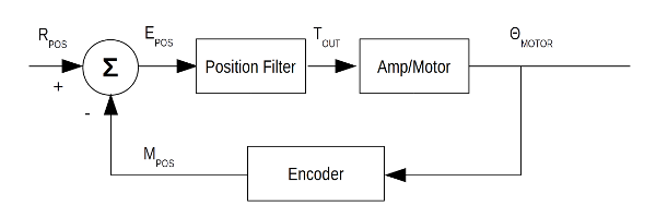
Figure 2: Position Control Diagram
The tension control loop is implemented around the position loop. Figure 3 shows the control loop including tension control. The error in tension (ETEN) is calculated by the difference in the reference tension value (RTEN), which in this application is a static value, and the measured tension (MTEN). After filtering the error value, a jog speed is issued (RVEL) to drive the tension error to 0.
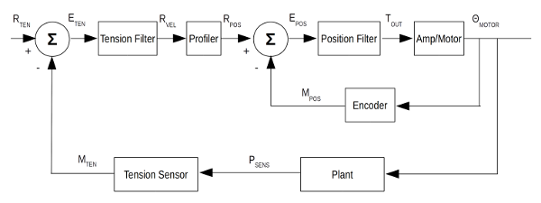
Figure 3: Tension Control Diagram
This application setup was implemented and tested using Galil's high-performance DMC-40x0 motion controller. As part of a Galil motion controller, the position loop and motion profiler is embedded in the controller's firmware, therefore, the motion code needs to have a simple loop that follows the flow chart shown below in Figure 4 to implement the tension control.
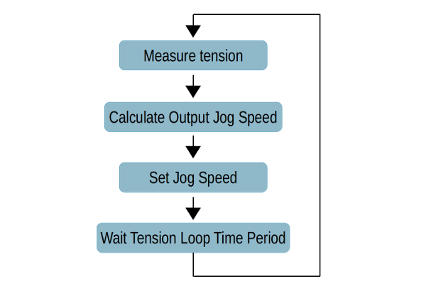
Figure 4: Tension Loop Flow Chart
The system setup used to demonstrate this tension control application includes two spindles, the master on the B axis and the slave on the A axis. The tension sensor returns a quadrature signal, which is wired to the main encoder input on the C axis.
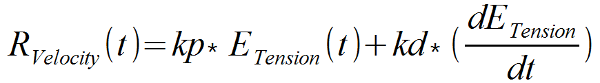
Since the tension loop is a lower-bandwidth loop over the position loop, the sample time period for the tension loop should be greater than that for the position loop. For this case, the period for the position loop is 1ms, while the period for the tension loop is 10ms. The filter implemented for the tension loop is a PD filter. Therefore, every loop the controller measures the tension error, the derivative of the position error, and sets the jog speed of the slave axis based on the following equation.
This was implemented on the DMC-40x0 motion controller with the following Galil DMC code:
#tnsn
kp= 140;' tension loop P coefficient
kd= 380;' tension loop D coefficient
JGB= 0;BG B;' begin jog on B axis with speed 0
old= 0;' initialize variable
AT 0;' establish initial time reference
#loop
er= _TEC;' capture tension error from tension encoder
ddt= er-old;' calculate d/dt error
JGB= (er*kp)+(ddt*kd);' set jog speed
old= er;' set error to previous value
AT -10;' loop time is 10msec
JP #loop;' loop back to #loop
To test the response of this tension loop, a step profile was used for the reference tension. The reference tension (_RPC), measured tension (_TPC), tension error (_TEC), and slave axis velocity (d/dt _RPB) are all plotted below in Figure 5 using Galil's GDK software suite.
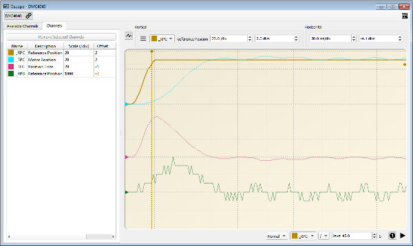
Figure 5: Tension control loop step response
Knowing that the tension loop period is 10ms, the result of this plot shows that the tension moves and settles within about 8 samples (80ms), demonstrating an effective system response.
Electronic Gearing with Tension Control
Revisiting the original problem, the slave axis is geared to the master axis and is constantly varying the effective gear ratio to maintain tension. This can be fully implemented by taking the superposition of the tension loop profile and a static gear ratio. With Galil's DMC-40x0 controller, the electronic gearing mode is superimposed to any other mode of motion on that axis. Therefore, gearing can be set with 2 commands and the tension loop will correct for any errors or disturbances to maintain constant tension. This is shown below in the following code.
GA ,CA;' axis B is geared to commanded position of axis A
GR ,2;' gear ratio is 2 (axis B twice resolution of A)
#tnsn
' continue with tension loop code
Figure 6 shows the response of the full system when the master spindle is at a constant speed. The speed of the master axis is 2048 counts/sec and is shown in yellow on the graph below. The slave axis (blue) has a gear ratio of 2, so the nominal speed would be 4096 counts/sec. The plot shows that the actual speed is slightly varying around that nominal speed of 4096. This is due to the tension control loop. The tension error (magenta) is consistently within 7 counts of the reference tension during the performance of the system.
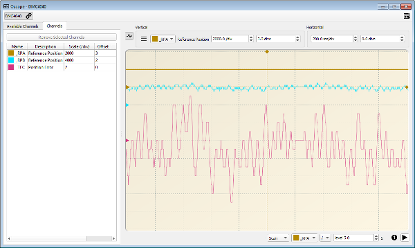
Figure 6: System response
Conclusion
Using electronic gearing with Galil's motion controllers greatly simplify this type of tension control application. Moreover, this approach can solve other application challenges where a lower-bandwidth feedback loop is over the motion profiling and position loops. This is one example of how electronic gearing can be used in a much wider set of applications. Following papers will discuss other challenges that can be simplified with electronic gearing.