Video 1: Galil's New H-bot Firmware in Action.
There are many applications that require movement in planar space, or movement along two perpendicular axes. This two dimensional system can be fitted with additional motors to increase the number of degrees of freedom. These types of applications can range from specimen positioning for a microscope and 3D printers to product packaging and material application. The most common way that planar motion is achieved is using a machine based on the XY stage or gantry system. This type of system can have many drawbacks which will be outlined later in this article. An alternative to these types of machines is the H-Bot which has many advantages when compared to XY stages or gantries. This article will discuss the advantages and disadvantages of using an H-Bot for systems that use planar movement as well as Galil's H-Bot firmware solution for the DMC-40x0.
When an engineer or a machine designer has the need to move a load in a plane, one motor can be fitted to move a load in one direction. Two of these single axis systems can be stacked orthogonally to achieve planar motion. There are many ways for a single motor to move along an axis; lead screw, linear motor, belt drive, rack and pinion and others. If the load is too heavy to reliably move with one motor then two can be used to move along a single axis. This arrangement is known as a gantry system. Both the stacked XY stage and gantry system can be seen in Figure 1.

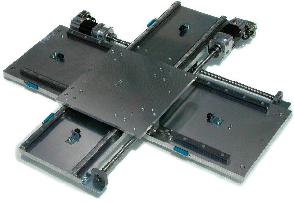
Figure 1: XY Gantry System (Top) and XY Stage System (Bottom).
Stacking orthogonal systems in this manner has many drawbacks. Lead-screws are expensive and introduce additional friction which requires larger, more expensive motors to move the system. Linear motors can be substantially more expensive than rotary motors. Mounting this system becomes complex because one system must ride on top of the other. Mounting for these systems have increased design and manufacturing complexity, resulting in extra machine cost. With one axis riding on top of the other, the systems inertia is increased and the load on one motor is disproportionate to the other. The load on each motor changes with its position in some XY stages and the additional loading that results can cause inconsistent or large displacement errors at the ends of travel. Some of these can be addressed with the gantry, which has the cost disadvantage of incorporating an additional motor.
Position error can also occur from misalignment of the orthogonal axes. This adds tighter component tolerances which increases manufacturing cost. Changing the length of travel for these systems once designed is usually difficult to impossible, making them less flexible with systems that need to be modular. When using lead screws, motors must be mounted inline which can create service issues if the machine is in close proximity to other machines or a wall. Lastly, XY stages have a low workspace to total space ratio, meaning that they take up a large amount of space relative to the space that can be utilized for movement and positioning.
An alternative to the stacked system is the H-Bot, which brings with it many advantages when compared to the XY table or gantry. The H-Bot, as seen in Figure 2 closely resembles the gantry with a few distinct differences. Two motors are used to move a serpentine belt that is fed through a system of pulleys. This belt is clamped to the carriage and moves on a guide along a single axis. This guide is then mounted to two other sets of guides similar to that of the gantry to allow movement in the orthogonal direction. The carriage is moved in the XY plane though a coordinated feeding of the serpentine belt around its pulley system.
This is in contrast to the XY table where X or Y axis motion is achieved by moving a single motor controlling that axis. H-Bots can be designed to provide the same functionality of an XY stage or gantry without many of the drawbacks.
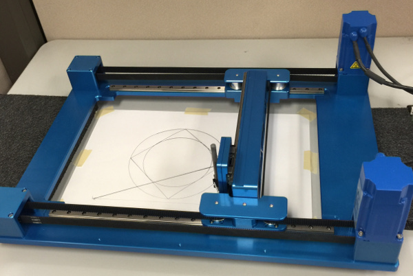
Figure 2: H-Bot System.
The planar motion of the H-Bot can be combined with other components and allows it to be adapted to many types of applications. Uses for the H-Bot can include: point to point positioning, pick and place, material filling and application, planar or three dimensional cutting, and many others. How the carriage or load is positioned is best illustrated with a schematic showing one form of its construction.
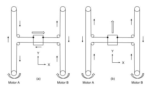
Figure 3: H-Bot vertical and horizontal motion.
Figure 3 shows that the carriage, depicted as a square, is connected on either side by a serpentine belt. This belt is fed through a total of 6 pulleys and 2 motors. The carriage will slide (left and right) along a gantry that is free to move up and down, which allows for complete planar freedom. Figure 3a illustrates how a move in the +X direction can be accomplished by turning both motors in the clockwise direction, by the same amount, and at the same speed. Figure 3b illustrates how a move in the +Y direction can be accomplished by turning both A and B motors by equal amounts in opposite directions and at the same speed. Non-orthogonal motion requires contributions from both of these fundamental moves by both motors. Determining the motor position required to attain a final position is mathematically defined and is what is known as inverse kinematics.
There are many features that can make the H-Bot an ideal choice over a XY stage or gantry:
1. Increased ratio of usable workspace to overall machine size. Because the construction of an H-Bot uses a serpentine belt and pulleys, the overall size of the system is reduced greatly for a given workspace. Motors are often mounted perpendicular to the working plane which saves planar space. Unlike a XY stage, the orthogonal axes are not stacked which can save in vertical space as well.
2. Overall cost reduction due to multiple factors:
- Less expensive pulleys or sprockets are utilized instead of lead screws.
- Belts cost significantly less than a lead screws or linear motors, which reduces investment and maintenance costs.
- The axes are not stacked on top of one another like a XY stage or gantry. This reduces the overall weight and complexity of the system. This reduction in components and material saves in the H-Bots' construction costs. Reduction of weight allows smaller motors to be sized, bringing additional savings.
- Having a light weight construction has the added benefit of increased throughput of the system with less mass to accelerate.
3. Two motors share the same load, similar to a single axis gantry. This load sharing makes the system balanced, therefore two identical motors can be used.
4. Replacing lead screws with belt drive will reduce friction in the system. This will reduce ware and maintenance costs as well.
5. The H-bot can be constructed modularly. The work area can be made larger or smaller depending on the length of rails and a longer belt. The addition of an intermediate idler pulley to maintain tensions and support the belt may be required.
6. Changes to the speed or accuracy of the system can be done by changing the drive pulley diameter which is often easier than changing the lead screw pitch or encoder resolution.
7. The position of the motors can be arranged to accommodate space or accessibility restrictions.
8. Less expensive rotary motors can be used in lieu of expensive linear motors.
With all the advantages that the H-Bot brings over a standard XY system there are drawbacks. The main disadvantage is that the motion of an H-Bot requires that meaningful XY coordinates or motion be converted into motor positions and motor motion. This adds computational complexity to the control of the machine because any and all motion must be coordinated between two motors. In addition to profiling motion on two motors, both motors should be turned on and off simultaneously. Because of this coupled construction, additional safety considerations must to be taken for limits, bringing the system to a stop when a limit is hit must involve coordinated deceleration of both motors. The serpentine belt can introduce load position error due to flexibility. This type of error is similar to the backlash that will be found on a lead-screw and can be minimized by using high quality, reinforced belts at a proper tension.
Galil has eliminated the computational complexity and safety considerations by developing an H-Bot firmware for the DMC-40x0 that makes operation of an H-Bot transparent to the user. For the following section, use of Galil's two letter command syntax is used in conjunction with a description of the command. When the position is defined (DP) or reference position queried (RP), it is always done in planar XY coordinates. Because the two motors are coupled, both motors are always engaged (SH) and disengaged (MO) simultaneously, even if only one of the two is commanded to do so.
Single axis or independent motion commands used in a XY stage are used on the H-Bot with the same resulting motion. Issuing a jog (JG), relative (PR/IP) or absolute position (PA) move along a single axis will coordinate the motion of both motors to achieve the desired motion profile in that direction. Commanding vector moves (VM) uses the same syntax and commands as the standard XY system. As with the independent moves, both motors are coordinated to achieve the desired vector motion. The motor or the XY axis position can be used in gearing as well, making the H-Bot flexible enough to be adapted to applications using electronic gearing and additional motors. Triggering a limit switch will always result in the coordinated deceleration of both motors to bring that axis to a stop. The off-on-error (OE) feature will affect both motors as well.
Homing the H-Bot is done through the use of the find edge (FE) command to find the transition of the home switch. As with all Galil controllers, there is freedom for custom homing sequences as well. The PID filter has also been modified to aid with tuning the system for the desired response. The feed forward velocity (FV) and feed forward acceleration (FA) are specified for XY axes not individual motors. Both motors share the loading of the system but there is a different amount of inertia when moving the carriage or when moving the gantry. Having the feed forward bias apply to axes rather than motors allows these inertial differences to be compensated for in the control loop. The total amount of bias that is applied to each motor depends on the feed forward gains for the XY axes and the component of either velocity or acceleration along those axes. This change to the PID loop is necessary to achieve the advantage of the feed forward gains on the H-Bot system.
In conclusion, an H-Bot brings many added benefits to an application that uses planar motion. This planar motion can be combined with other axes in the same way that a stacked XY system can. The construction of an H-Bot is simplified compared to the standard XY solution which results in less total components, material, weight, cost, and maintenance. These are all major advantages over the XY stage or gantry. The drawbacks of using an H-Bot in an application comes from its parallel or coupled motor construction requiring a more complex control solution. Galil has developed firmware that addresses these complexities and makes controlling an H-Bot, from a user perspective, indistinguishable from that of the standard system. Switching an existing application to this type of system from an XY system can be done with minimal changes to existing programs. Both new and existing H-Bot systems can benefit from the ease of use that the Galil H-Bot firmware brings.
If you are interested in utilizing Galil's new H-bot firmware in your new or existing application, please contact Galil's experienced support team either by email (support@galil.com) or by phone (916-626-0101 or 800-377-6329(US Only)).